8 Considerations When Designing a Wood Railing with Cable Infill
When designing a wood railing with cable infill, there are a few things at play that you need to be mindful of. Here are the 8 considerations when designing a wood railing with cable infill:
1. Construction and Location of Your End (Terminating) Posts
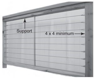
An end post is a post to which terminating cable ends are attached with tensioning or non-tensioning hardware. Considerable tension is applied to the end posts when the cable is properly tensioned. A substantial end post is necessary, to prevent the end post from bending, which will cause the cables to sag. With wood, a minimum 4×4 (3-1/2” square) end post is required.
End posts must be securely fastened to the deck or another surface, to prevent the post from coming loose from the forces applied through the tensioned cables. Support members between end posts are also necessary. With wood, we recommend support members running between posts, such as a 2×4 secured to the inside of each post, so you are not relying on the shear strength of the nails or screws to support the tension applied to the end post.
2. Configuration of Any Corners in Your Design
At corners or turns of more than approximately 45°, it is best to terminate your runs in each direction with an end post. These illustrations demonstrate how this is done:
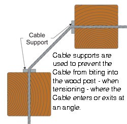
A stainless steel flat bar (cable support) with holes for the cable to pass through is mounted on each surface where the cable enters or exits the post at an angle to prevent the cable from biting into the wood when it is tensioned. Cable supports are available from Wagner.
We do not recommend using this type of corner post configuration on more than one corner between any two-end posts (with tensioning hardware). When using this configuration, you will need tensioning hardware on both ends of the run, and you will need to tension the cables from both ends.
On a turn of less than approximately 45°, you can run your cables through a single post, but you will still need to use a cable support where the cable enters or exits the post at an angle to prevent the cable from biting into the wood when it is tensioned.
See #8 below for other hardware combinations that can be used on corner posts.
3. Location of Intermediate Posts
Intermediate posts (or mid-posts) are placed between end posts. An intermediate post runs from the top rail to the lower mounting surface and is a structural element. Intermediate posts should be placed at intervals between the end or corner posts as frequently as necessary to meet load requirements. An engineer or design professional should be engaged if you are unable to otherwise determine intermediate post spacing.
Cable is strung through holes drilled in the intermediate posts, so intermediate posts also become supports for the cable between end posts.
With cable spaced vertically on centers as recommended below (see #6 spacing of cables on your end post below), we recommend that the cable is supported in some manner no more than every 42” along its run. The support can be provided by an intermediate post or it can be something thinner such as a 2 x4 or a thin steel cable brace (noted in the next section).
4. Location of Additional Cable Supports
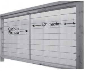
Regardless of the amount of tension you apply to the cables, there will be some flex in the cable when it is installed. When the cables are spaced vertically on your end post, we recommend that the cable is supported in some manner no more than every 42” along its run. This support can be provided with intermediate posts or a lighter material acting as a cable brace.
As with an intermediate post, a cable brace also runs between the top rail and the lower mounting surface, but its purpose is only to support the cable. It is not intended to be an element providing structural support to the railing.
Cable braces can be much thinner and, therefore, less obtrusive than posts, as their primary purpose is only to support the cable. A ¼” x 1” steel flat bar, usually stainless steel, with holes drilled for the cables to pass through makes an excellent cable brace. Flat bar cable braces are available from Wagner.
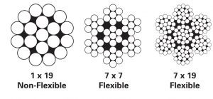
5. Cable Diameter to Use
It is important to use 1×19 construction cable as a railing infill because it is attractive, smooth to the touch and designed to support loads in tension with minimal stretch. The individual wires in 1×19 construction cable are much larger than those used in more flexible constructions. This makes the cable less prone to damage from abuse, and it is also the reason why the strand does not stretch as much as other constructions.
You will want to specify type 316 stainless steel because it is the most corrosion-resistant commercially available alloy used in manufacturing cable. Our cable railing hardware is made of type 316 stainless steel, so no material compatibility issues will arise when you use type 316 stainless steel cable with our hardware.
It is also important to use at least a 3/16” diameter cable. Problems have been experienced with damage from abuse when 1/8” diameter cable has been used. Following are the minimum breaking strengths of type 316 stainless steel cable.
| Cable Diameter | 1x 19 | 7×7 | 7×19 |
| 1/8” | 1,780 lb | 1,360 lb | 1, 300 lb |
| 3/16” | 4,000 lb | 3,300 lb | 2,900 lb |
| 1/4″ | 6,900 lb | 5,500 lb | 4,900 lb |
As the chart above illustrates, for a small increase in size (and cost) you can more than double the strength of your infill and ensure that damage from abuse is not an issue with your railing. Everything considered, 3/16” diameter 1×19 construction type 316 stainless steel cable is usually the best choice for most railing applications.
6. Spacing of Cables on Your End Posts
Even though you use 1×19 construction cable and the cables are properly tensioned on a strong end post, there will be some flex in the cable when a load is applied.
The spacing of the cable on the end posts works together with the distance between points where the cable is supported, to minimize cable flex. The closer together the cables are spaced on the end posts, the longer the distance can be between cable support points. The inverse is also true.
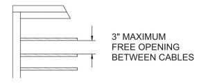
Weighing the wish to use as few cables as necessary with the need to minimize cable flex, we recommend maximum vertical spacing of the cables on your end posts so there is no more than a 3” free opening between cables.
For example, if you are using 3/16” cable, you should mount your cables on the end posts on a maximum of 3-3/16” centers.
7. Whether to Cut Cables and Put Fittings on in the Field or Use Factory Cut Cables
Cables can be cut and swaged (fittings put on cables) in the field using swagers and installation tools purchased or rented from us, or they can be provided from us cut to length with the fittings attached, ready to install.
Field Swaging
Swaging in the field offers many advantages over having the cables cut and swaged at Wagner. The first advantage is that the holes the cables pass through in your intermediate posts do not have to be any larger than is necessary for just the bare cable to pass through.
If you have fittings already attached to both ends of the cable, your intermediate post holes must be at least as large as the diameter of the smallest fitting attached to the cable. The difference between the hole and cable diameters will be 1/16” or more, which will cause more cable deflection than the tighter fit obtained if the fittings are swaged on site.
The second advantage is that there is no need to provide accurate measurements to a second party who is doing the cutting and swaging of the cables. Field swaging eliminates the possibility of misinterpreting your dimensions.
In the field, the cables are cut to a slightly longer length than necessary and one end fitting is swaged onto the cable and attached to an end post. The cable is then strung through the railing frame. The bare end is pulled tight at the opposite end post and marked with a permanent marker for cutting. The second end fitting is swaged onto the cable. The cable is tensioned, and you are done. You do not have to wait for someone else to make the cables and ship them to you and take the chance that some of them may not be cut correctly.
Most importantly, you are in control of when the cables are done. Field swaging is easy, using swagers and tools available for purchase or rental from Wagner. Complete instructions are included with all orders.
Factory Swaging
If the cables are cut and the fittings swaged by us, you do not need to use special equipment. There is a charge for factory cutting and swaging, but for smaller jobs, the cost will be less than renting the equipment required to field swage the cables.
Some cable hardware is designed to pass through holes in your intermediate posts that are drilled as little as 1/16” more than the diameter of the cable when both ends are swaged by us. You will find these fittings outlined in the following section. Where the cable will not pass through any intermediate posts, you can order factory-cut and swaged cables using any hardware. You are not limited to the fittings you can use.
8. Selection of Appropriate Hardware
In selecting hardware, there are a few things you will want to consider.
- whether you want to field cut and swage the cables or have them factory cut and swaged
- what hardware preferences do you have for end posts
- how you wish to configure your corners (if applicable)
- what hardware should be used for stairs or severe slopes
1. Field cut and swage or factory cut and swage for cable fittings
See #7 above to determine whether you will be field cutting and swaging or if you want Wagner to cut the cables and swage on the fittings. When the fittings are swaged on at the factory, some fittings are larger in diameter than the size of the holes you want to drill in your intermediate members (posts or cable braces).
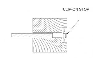
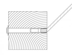
The fittings illustrated below require relatively small holes in your intermediate members. If the hardware is swaged on at the factory and if the cable passes through intermediate posts or cable braces, one end of each cable should have one of the following fittings. The holes in your intermediate member will be drilled for the diameter of the swaged fitting passing through the intermediate member as shown in the following illustrations:
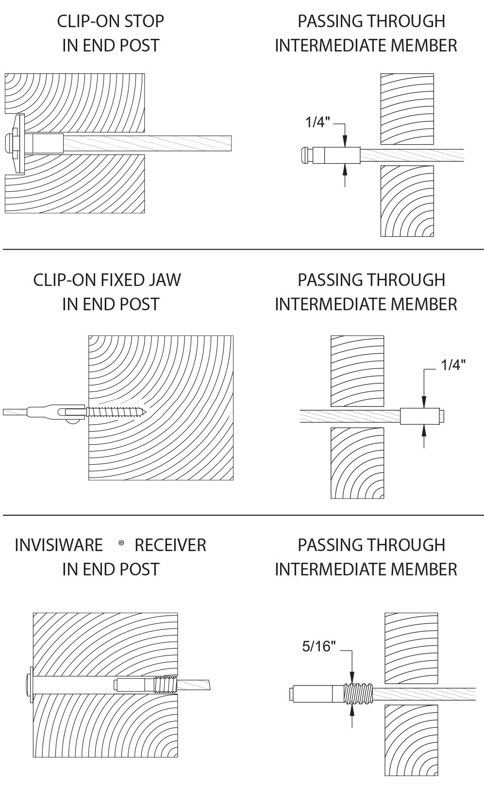
Where the cable will not pass through any intermediate members, you can order factory-cut and swaged cables using any hardware. You are not limited to the fittings shown above. If your cables will be cut and the fittings swaged on at the factory, you will need to provide us with measurements for your cable runs after the posts have been installed. Contact Wagner for the measurements required.
2. Mounting hardware for end posts
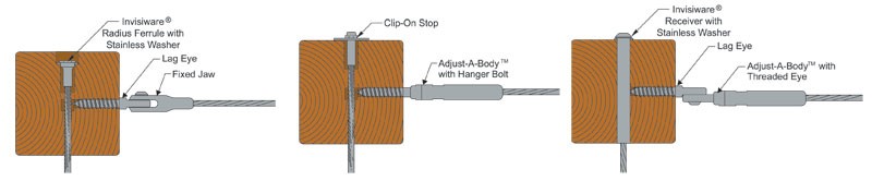
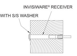
If you are mounting hardware on two sides of your corner posts, then your corner posts are considered end posts for this discussion. You will need to put tensioners on at least one end of each cable run. Following are tensioning devices. Note: With the Invisiware® Receiver, you will need up to 3-3/4” of space between the back of your end post and any structure to insert the fitting into the end post from the back side.
The other end of each cable run can be either a tensioner (above) or a non-tensioning device. The following are non-tensioning devices.
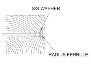
Note: With the Radius Ferrule, you will need approximately 2-1/2” of space between the back of your end post and any structure to insert the fitting into the end post from the back side.
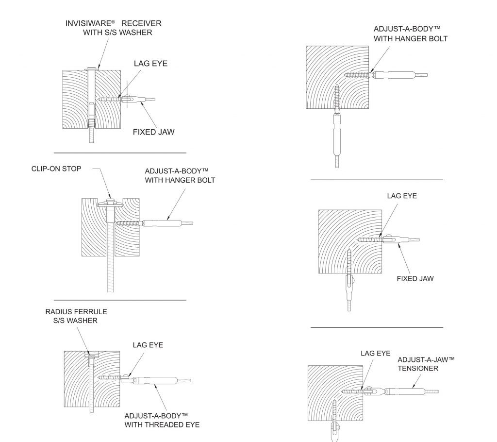
3. Corner configurations
See #2 above for ways to treat your corners. The following illustrations demonstrate how the hardware can be used on a single corner post. They also illustrate how some hardware can be countersunk into the post or mounted flush with the back of the post.
Not all combinations are shown here. If the hardware and cable run all the way through the post in one direction, you will need to use a hanger bolt end or hardware that is mounted to a lag eye for the perpendicular direction, as shown in the first three illustrations that follow.
4. Hardware needed for stairs or severe slopes
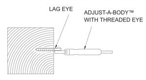
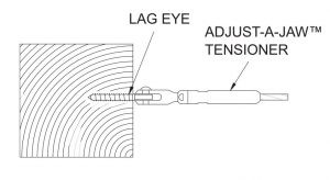
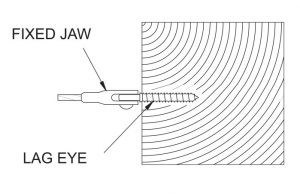
You can use any of the fittings with a fork or an eye in conjunction with a Lag Eye, to accommodate stairs and slopes. These fittings are Adjust-A-Jaw® and Adjust-A-Body™ with Threaded Eye tensioners and the Fixed Jaw non-tensioning fitting.
On pitches up to 35°, you can also use CRR662 Invisiware® Receivers on your 4×4 (3.5” square) end posts without having to drill your holes at an angle.
Invisiware® Receivers are less expensive than fittings with fork or eye ends and do not require lag eyes and screws to mount them. When installed, they are hidden inside the end post to help preserve that special view. CRR662 Invisiware® Receivers can be an excellent choice for stairs and slopes as well as straight runs.
These drawings illustrate some of the ways our cable railing hardware is used in wood end and corner posts. A minimum of a nominal 4 × 4 (3-1/2″ × 3-1/2″ actual) is recommended for any post where cable hardware is mounted.
If you have any questions, please contact Wagner today!